


DriveNets AI Fabric is a distributed network operating system (NOS). The solution manages a scheduled fabric supporting the highest performance AI networking at scale, with up to 32K GPUs (up to 800 Gbps each) per cluster, from any GPU vendor, with any Ethernet NIC.
This scheduled fabric AI backplane supports congestion-free operations, acting as a single Ethernet entity (with a single Ethernet hop from any GPU to any other GPU in the cluster) at any scale. It provides predictable, lossless connectivity with ultra-fast (microseconds level) failure recovery at scale. As a result, it delivers a proven >10% improvement in job completion time (JCT) for AI workloads at large-scale GPU clusters.
This post describes the capabilities of DriveNets AI Fabric and proposes a high-level reference design for an 8,000 GPU cluster, equipped with 400Gbps Ethernet connectivity per GPU. This design explores network segmentation, high-performance fabrics, and scalable topologies, all optimized for the unique demands of large-scale AI deployments.
GPU cluster network architecture
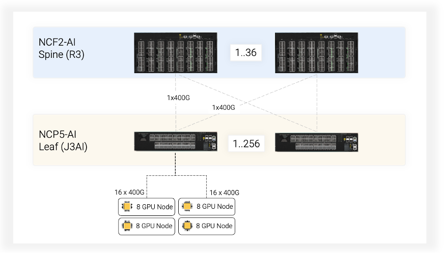
This high-performance GPU cluster utilizes a two-tier leaf-spine network topology designed for optimal performance and scalability in AI applications, leveraging the capabilities of DriveNets AI Fabric.
The leaf tier consists of DriveNets NCP5-AI leaf switches powered by Broadcom Jericho3-AI processors, while the spine tier consists of DriveNets NCF2-AI spine switches powered by dual Broadcom Ramon3 processors. The NCP5-AI leaf switches ensure efficient communication between GPUs within a server rack, while the NCF2-AI spine switches, with their high-performance Broadcom Ramon3 processors, facilitate traffic routing across the entire cluster.
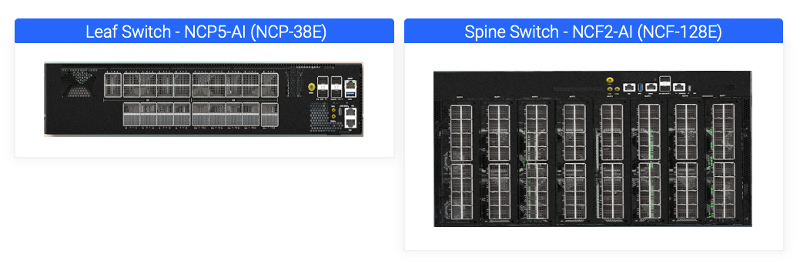
Leaf tier: Each NCP5-AI switch directly connects to multiple GPU servers. These switches serve a capacity of 30.4Tbps. Each switch is equipped with 18 ports that can be configured for 800Gbps or 36 ports of 400Gbps speeds, offering flexibility based on specific GPU connectivity needs. NCP5-AI utilizes 20x800G cell-switching ports for high-bandwidth uplink connections to the spine layer. Notably, these 800G ports can be broken out into 40 interfaces of 400G.
Spine tier: These NCF2-AI switches handle traffic routing between leaf switches using cell-switching technology for efficient load balancing. NCF2-AI offers a massive capacity of 102.4Tbps with 128x800G cell-switching ports. Similar to the leaf tier, these ports can be broken out to 400G interfaces. This breakout functionality increases the spine radix, allowing connectivity for up to 256 leaf nodes. With full 800G utilization, this design supports up to 32K GPU connections within the cluster.
| Leaf: NCP5-AI | Spine: NCF2-AI | |
| Network Interfaces | 18 x 800G OSFP | |
| Fabric Interfaces | 20 x 800G / 40 x 400G OSFP | 128 x 800G / 256 x 400G OSFP |
| Switching Capacity | 30.4Tbps (14.4T Ethernet + 16T Cell Switching) | 102.4T Cell Switching |
| Switching ASIC | Broadcom Jericho3-AI | 2 x Broadcom Ramon3 |
Building an 8,192 GPU cluster with DriveNets AI Fabric
This reference design allows for a highly scalable network thanks to DriveNets AI Fabric NOS and the breakout capabilities of NCP5-AI and NCF2-AI switches. The network can support up to 4,608 GPU connections with 800Gbps bandwidth in its base configuration. However, by leveraging 400G breakout on the leaf switches, one can connect up to 9,216 GPUs. (Typically, since only 32 [=8×4] of the 36 leaf ports are used, only 8,192 GPUs are connected.) Additionally, multitier spine functionality enables a network with up to 32K potential 800G GPU connections.
This section details how to construct a high-performance GPU cluster supporting 8,192 GPUs, each equipped with 400Gbps connectivity, leveraging the scalability of DriveNets AI Fabric NOS and the breakout capabilities of its NCP5-AI leaf switches.
Network configuration
- Leaf switches: This design utilizes 256 DriveNets NCP5-AI leaf switches, each with a capacity of 30.4Tbps, specifically designed for AI workloads.
- Leaf switch configuration:
- GPU connectivity: Each NCP5-AI switch directly connects to multiple GPUs. To maximize GPU attachment, we leverage 16 out of the available 18 ports with 800Gbps speeds on each leaf switch. These ports are broken out into 32x400G ports using DriveNets’ breakout functionality. This configuration enables each leaf switch to support 32 GPUs with dedicated 400Gbps connections.
- Fabric connectivity: While 32 uplink ports per leaf switch would suffice for GPU traffic, we utilize 36 available fabric ports for redundancy (N+1) and to accommodate additional traffic from Broadcom’s internal cell control packets. This translates to 32 ports dedicated to GPU traffic and 4 additional ports for redundancy and cell overhead.
- Spine switches: The number of required spine switches is determined by the total uplink capacity from the leaf switches.
Spine switch calculations
- Total uplink capacity: We calculate the total uplink capacity by multiplying the number of leaf switches (256) by the number of fabric ports per leaf switch (36): 256 leaves * 36 ports/leaf = 9,216 uplink ports (400Gbps).
- Number of spines: To handle this uplink traffic, we require 36 spine switches. This calculation is derived by dividing the total uplink ports (9,216) by the number of connections a single spine can support from a single leaf (256 x 400Gbps breakout ports per spine).
Rack elevation and data center layout
While data center deployments for GPU clusters can vary in design, key factors like power consumption and rack size play a crucial role. This reference design adopts a conservative approach, assuming a maximum power draw of 25kW per rack and utilizing a standard 48-unit rack size. This configuration aligns with common practices for high-performance GPU hosts like the NVIDIA HGX H100.
Network components
The solution comprises four key components:
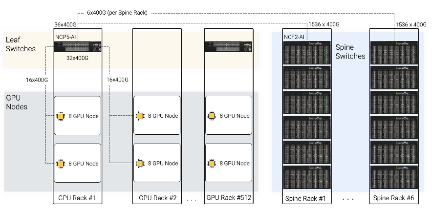
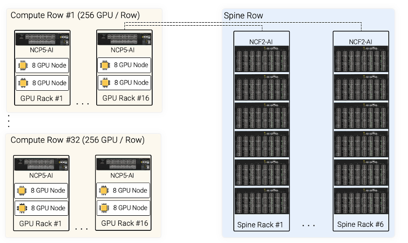
- Compute racks: These racks house the computational workhorses – the GPU nodes and the leaf switches. In this reference design, we consider a configuration with 2 GPU nodes per rack, each node supporting 16 Ethernet-capable GPUs (8 GPUs per node). This assumption aligns with typical data center practices, where a high-performance host like the NVIDIA HGX H100 might require around 11kW of power. Considering network and management switches, the entire rack’s power consumption would range from 22kW to 25kW. Since each leaf will support 32x400G GPUs, every two compute racks will connect to a single DriveNets NCP5-AI leaf switch.
- Spine racks: These racks house the spine switches. Each spine rack can contain 6 DriveNets NCF2-AI spine switches. These racks are usually located in a central location in the data center as all compute racks which house the GPU nodes and the leaf switches need to have connectivity to each of the spines in the network.
- Host NIC-to-leaf connectivity: Connectivity of GPU to leaf switch within the rack and between racks can utilize cost-effective direct attach copper (DAC) cables instead of optical fibers, leading to power and cost savings. In this design, a single NCP5-AI leaf will have 16x400G in-rack connections and 16x400G connections to the neighbor rack.
- Leaf-to-spine connectivity: Each rack equipped with a leaf switch will have 36 of its 400G links dedicated for connections to the spine switches. These spine switches reside in separate spine racks, typically designed to accommodate 48 rack units (RU). Each spine rack can comfortably house 6 DriveNets NCF2-AI spine switches. This design ensures that each leaf switch connects to every spine switch using a single 400Gbps link, resulting in a total of 6x400G connections per leaf switch to each spine rack.
Creating a highly scalable network foundation for an 8,192 GPU cluster
This reference design leverages DriveNets AI Fabric and the breakout capabilities of NCP5-AI leaf switches to create a highly scalable network foundation for an 8,192 GPU cluster. Each GPU benefits from a dedicated 400Gbps connection for efficient communication. The 256 leaf switches connect to 36 spine switches, ensuring redundancy and efficient traffic routing across the entire cluster.
This architecture can offer multiple ways to achieve low total cost of ownership (TCO). One way is by using copper instead of optics between leaf switches and GPU servers. The second and more important way is by reducing dramatically the end-to-end job completion time. This is part of the reason to use DriveNets AI Fabric solution in the first place, but that’s for another blog post.
Download white paper
Fabric-Scheduled Ethernet as an Effective Backend Interconnect for Large AI Compute Clusters